
Convex madness 02

It wasn't long and here we are again. This time we will implement some more basic operations with our polygon than we did already. To make things clear, let's make a list of what do we want to do with polygon:
- swap vertex order
- is polygon convex?
- is polygon planar?
- is polygon tiny?
- relative position of polygon against plane
- does polygon contain point?
- does polygon overlap with another polygon in the same plane?
- finding nearest point on polygon to another point
- is polygon hit by ray?
- split polygon by plane
- subtracting and intersecting polygons in plane
Swapping vertex order
Swapping vertex order is actually quite simple operation. Why do we want to do that at all? Someone maybe already noticed the normal direction depends on order of vertices (in case vertices are in clockwise order, normal vector points towards the viewer, in case vertices are in counter-clockwise order then normal points away from the viewer)
Someone figured out mechanism called backface culling which effectively skips polygons that has their normal vector pointing away from the viewer. It also can be interpreted as they are rotated away from viewer (they backface him) and they wouldn't be visible anyway because they are on back side of some object. This leads to elimination of practically half of polygons that would be normally drawn.
The algorithm is very simple, we just go from the beginning of vertex list (polygon vertex list, not the global one) to it's half and swap every vertex for it's opposite in the other half. I won't put here source code as this is really trivial.
Polygon convexness test
This is an easy one in case you know how to write it. As i mentioned at the beginning of the last issue, convex polygon is such a polygon with all it's interior angles less or equal to Pi radians. Now if you're thinking about sines and cosines, it's all wrong. Those functions are quite slow so it's always good to think of how to avoid them.
Imagine we are walking arround polygon on it's edges. In case polygon is convex, every edge has to turn towards the polygon centre. In case it turned away from the centre, the angle it holds with previous edge must be greater than Pi radians and therefore such a polygon is not convex.
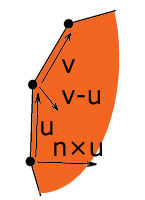 How do we determine wheter edge turns towards the polygon centre? We will simply calculate edge directions, subtract
next edge direction from current edge direction and the result is vector, pointing where the edge turns. Now it's
sufficient to find out wheter it points towards the centre or not. We need vector, perpendicular to the current
edge, pointing towards the center and then simple dot product tells us the truth. How to get such a vector?
Easily calculate cross product of edge direction vector and polygon normal, it will always point towards the
centre or away from it depending on edge dircetion vectors order in cross product.
How do we determine wheter edge turns towards the polygon centre? We will simply calculate edge directions, subtract
next edge direction from current edge direction and the result is vector, pointing where the edge turns. Now it's
sufficient to find out wheter it points towards the centre or not. We need vector, perpendicular to the current
edge, pointing towards the center and then simple dot product tells us the truth. How to get such a vector?
Easily calculate cross product of edge direction vector and polygon normal, it will always point towards the
centre or away from it depending on edge dircetion vectors order in cross product.
    /*
     *    bool b_IsConvex() const
     *        - returns true in case polygon is convex, otherwise returns false
     */
    bool b_IsConvex() const
    {
        Vector3f v_u = (Vector3f)m_vertex_list[m_vertex_list.size() - 1] -
            (Vector3f)m_vertex_list[0];
        v_u.Normalize();
        for(int i = 0; i < m_vertex_list.size(); ++ i) {
            Vector3f v_v = (Vector3f)m_vertex_list[i] -
                (Vector3f)m_vertex_list[(i + 1) % m_vertex_list.size()];
            v_v.Normalize();
            // get two edge vectors ...

            if(v_u.v_Cross(m_t_normal.v_normal).f_Dot(v_v - v_u) < -f_epsilon)
                return false;
            // see if difference vectors goes to the same side as cross
            // product of first edge vector with normal

            v_u = v_v;
        }

        return true;
    }
Polygon flatness test
Tiny polygon test
How tiny is a tiny polygon? It may sound a bit vague, but it's very important function because when performing some kind of spatial subdivision, one offen gets very small pieces of polygons. But they can't be infinitely small because our floating point arithmetic is not precise enough and after certain limit, polygon will be just a group of points at the same location. To avoid this we need some kind of test to tell us wheter we can subdivide polygon even more or if it's impossible.
The function is very simple as well, tiny polygon should have at least three edges, longer than epsilon. That's actually all the magic.
Relative position of polygon against plane
Polygon can be either 'in front of', 'behind' the plane, it can lie on plane or it can be split by the plane. Determining which one of these conditions occured is actually pretty simple, it's just necessary to count numbers of vertices in front of plane and number of vertices behind the plane. In case vertex lies on the plane, do nothing. Then in case either front or back counter is zero, polygon lies behind or in front of the plane respectively. In case both counters are zero, polygon lies on the plane. And at least in case both counters are nonzero, polygon is split by the plane.
Included source code utilizes std::for_each cycle as it's simple to understand and it's recommended to use for_each rather than handcrafted cycles. (note i may use handcrafted cycles in this or any other issue and it's only because not every algorithm is suitable for for_each and it's mostly better understandable this way as well)
Point in polygon test
There are several common ways to determine wheter point lying on triangle plane is inside of it.
Actually very simple method is to calculate vectors from the point to all vertices of the polygon and sum angles they hold. In case point is inside the polygon, the sum must be 2Pi (180 degrees). This method however requires arc-cosine function and is generally very imprecise. For the sake of clarity, i'm adding source code for you to see how it works. Avoid using this method.
    /*
     *    bool b_PointInside_SumAngles(Vector3f v_point) const
     *        - returns true in case point v_point is inside the polygon
     *        - uses method of summing up point-to-edge vector angles
     */
    bool b_PointInside_SumAngles(Vector3f v_point) const
    {
        float f_angle_sum = 0;

        Vector3f v_prev = (Vector3f)m_vertex_list[m_vertex_list.size() - 1] - v_point;
        v_prev.Normalize();
        for(int i = 0; i < m_vertex_list.size(); ++ i) {
            Vector3f v_cur = (Vector3f)m_vertex_list[i] - v_point;
            v_cur.Normalize();
            // take two vectors ...

            f_angle_sum += (float)acos(v_prev.f_Dot(v_cur));
            // sum up the angles they hold

            v_prev = v_cur;
        }
        // sum up the angles

        return fabs(f_angle_sum - 2 * f_pi) < f_epsilon;
        // in case difference from 2pi is less than epsilon, the point is inside
    }
Another, also very easy to understand and actually quite precise method uses planes, placed onto polygon edges orthogonaly to polygon normal plane. This creates 'fence' and we have only to check wheter point is on the inner side of every plane (inside the fence). Note point doesn't need to lie on polygon plane (as previous method requires) it's enough if his orthogonal projection does. I'm again adding source code for you to see how this can be optimalised (i'm using the same method i used for determining wheter polygon is convex) As this method is really easy to understand and might be even fast, sometimes it's sufficient:
    /*
     *    bool b_PointInside_EdgePlanes(Vector3f v_point) const
     *        - returns true in case point v_point is inside the polygon
     *        - uses method of edge planes 'fence'
     */
    bool b_PointInside_EdgePlanes(Vector3f v_point) const
    {
        for(int i = 0; i < m_vertex_list.size(); ++ i) {
            Vector3f v_u = (Vector3f)m_vertex_list[i] -
                (Vector3f)m_vertex_list[(i + 1) % m_vertex_list.size()];
            // get an edge vector ...

            Vector3f v_v = v_point - (Vector3f)m_vertex_list[i];
            // get vector to point

            if(v_u.v_Cross(m_t_normal.v_normal).f_Dot(v_v) > 0)
                return false;
            // see if the point lies behind the 'fence' plane
            // (in case it does, it's outside)
        }

        return true;
    }
And at last, but definitely not at least there are barycentric coordinates. They are actually pretty handy because along with intersection information we could easily interpolate vertices using barycentric coordinates. Anyway, what are those and how to calculate them?
Barycentric coordinates are coordinates in triangle. Let's call them u and v. Every point on triangle or outside triangle can be calculated as linear combination of two of triangle's edges (assuming the triangle has three non-zero, non-colinear edges):
p = u * edge1 + v * edge2
Where edge1 and edge2 are edge vectors defined as:
edge1 = vertex2 - vertex0
edge2 = vertex3 - vertex0
If you think about it for a while, it's actually quite simple to determine border conditions. Triangle is bordered by it's three edges. Line equation for edges 1 and 2 could be:
vertex0 + u * edge1; u >= 0, u <= 1
vertex0 + v * edge2; v >= 0, v <= 1
This assumes both edges originate in vertex 0 of the triangle. Those were two sides, anyway. What about the third? We can define the third one as line between triangle vertices 2 and 3. Such a line could have equation:
vertex2 * w + vertex3 * (1 - w); w >= 0, w <= 1
If you think about it some more, vertices 2 and 3 can be expressed as:
vertex2 = vertex0 + 1 * edge1
vertex3 = vertex0 + 1 * edge2
And border line equations above can be rewritten as:
vertex0 + u * edge1; u >= 0, u <= 1
vertex0 + v * edge2; v >= 0, v <= 1
vertex0 + u * edge1 + v * edge2; u >= 0, u <= 1, v >= 0, v <= 1, u + v <= 1
That gives us three basic conditions u >= 0, v >= 0, u + v <= 1. In case these conditions are met, point lies inside the triangle. But how to calculate them? Perhaps look at their graphical representation:
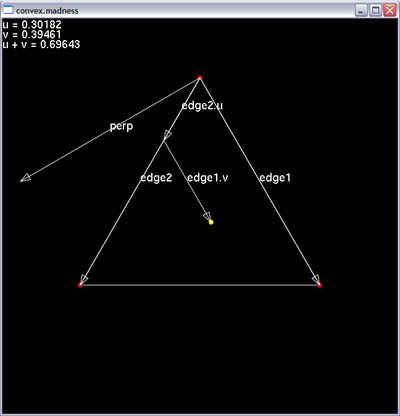
You can see vectors edge1 and edge2 and their versions, scaled by u and v respectively, pointing at the yellow dot. The yellow dot is point whose barycentric coordinates we are interested in. But how to calculate them? It's actually not so hard. We begin with constructing vector, perpendicular to edge1, marked as perp. We create vector from vertex 0 (the top most) to yellow point and project it to perp. (notice orthogonal projection of yellow point to perp would be in the single line with edge1.v) Then we take projection distance, divide it by dot product of perp and edge2 and voila, we have the u coordinate. Now it's necessary only to scale edge2 by u and calculate the vector edge1.v (by subtracting edge2.u from vector leading from vertex 0 to yellow point) Once we have edge1.v, we comapre it with edge1 and we have v as well. In case vertex is inside the polygon, we can calculate one more coordinate, w = 1 - u - v and we can use them to scale triangle vertices for example to interpolate texture coordinates in place where the yelow point lies.
I'm adding the code as well so it's more clear. The above image is printscreen from part of today's demo.
Vector3f v_edge1 = vertex_list[1] - vertex_list[0],
         v_edge2 = vertex_list[2] - vertex_list[0];
float f_inv_length2_edge1 = 1.0f / v_edge1.f_Length2();
Vector3f v_perp = v_edge2 - v_edge1 * (v_edge1.f_Dot(v_edge2) * f_inv_length2_edge1);
float f_rescale = 1 / v_perp.f_Dot(v_edge2);
Vector3f v_t = v_yellow_point - vertex_list[0];
float f_u = v_t.f_Dot(v_perp) * f_rescale;
float f_v = (v_t - v_edge2 * f_u).f_Dot(v_edge1) * f_inv_length2_edge1;
// calculate barycentric coordinates for the yellow point
Till now, we've been talking about triangles. But what if we don't have just triangles? It's sad but calculating baryctentric coordinates for polygons would be just far too much complicated so it's necessary to handle polygon as group of triangles and repeat the calculation several times with different edges. We're going to use barycentric coordinates once more when raytracing polygons.
Here is final barycentric point-inside-polygon test: (note it would be propably slower than planes 'fence' approach, but it tends to be more robust in case of not-quite-convex polygons)
    /*
     *    bool b_PointInside_Barycentric(Vector3f v_point) const
     *        - returns true in case point v_point is inside the polygon
     *        - uses barycentric coordinates and polygon to triangles decomposition
     */
    bool b_PointInside_Barycentric(Vector3f v_point) const
    {
        for(int i = 1; i < m_vertex_list.size() - 1; ++ i) {
            const TVertStruct *p_vert0 = &m_vertex_list[0];
            const TVertStruct *p_vert1 = &m_vertex_list[i];
            const TVertStruct *p_vert2 = &m_vertex_list[(i + 1) % m_vertex_list.size()];

            Vector3f v_edge1 = (Vector3f)*p_vert1 - (Vector3f)*p_vert0,
                     v_edge2 = (Vector3f)*p_vert2 - (Vector3f)*p_vert0;
            float f_inv_length2_edge1 = 1.0f / v_edge1.f_Length2();
            Vector3f v_perp = v_edge2 - v_edge1 * (v_edge1.f_Dot(v_edge2) *
                f_inv_length2_edge1);
            Vector3f v_t = v_point - (Vector3f)*p_vert0;
            float f_u = v_t.f_Dot(v_perp) / v_perp.f_Dot(v_edge2);
            // calculate barycentric coordinates for v_point

            if(f_u < 0)
                continue;
            // first condition failed

            float f_v = (v_t - v_edge2 * f_u).f_Dot(v_edge1) * f_inv_length2_edge1;
            if(f_v >= 0 && f_u + f_v <= 1)
                return true;
            // in case the other conditions are satisfied as well, point lies inside
        }

        return false;
    }
Polygon - polygon overlap test
This test is quite intuitive, in case polygons overlap, one polygon must contain some of other polygon's edges (not vertices!). Polygon-edge collision detection is rather tricky, and so the implementation uses the method of separating axes (briefly covered in the next part of the series, not very demanding for implementation).
Nearest point on polygon
Nearest point on polygon is handy for example for collision detection but can also have other uses such as subdivision point to be used for per-vertex lighting. (it's good to subdivide your polygons so they have vertex located in position of point nearest to light, that way hightlights will look better) Finding nearest point on polygon is quite simple. It's only necessary to project input point onto polygon normal plane and see if projected point lies in polygon's interior. In case it does, it's nearest point on polygon. (note with edge planes fence it's possible to save point projection)
On the other hand in case point didn't lie on polygon, it's necessary to find nearest point as orthogonal projection on one of polygon's edges. I suppose everyone can find projection of point on edge, but just to remind, projection can be calculated as edge vector, multiplied by dot product of edge vector and vector from edge origin to point in question. Note edge vector should be unit length, but that's easy to workarround. Folowing source code demonstrates that.
    /*
     *    Vector3f v_NearestPoint_Barycentric(Vector3f &r_v_vector) const
     *        - returns nearest point to r_v_vector contained by polygon
     */
    Vector3f v_NearestPoint_Barycentric(Vector3f &r_v_vector) const
    {
        Vector3f v_projection = r_v_vector - m_t_normal.v_normal *
            (m_t_normal.v_normal.f_Dot(r_v_vector) + m_t_normal.f_dist);
        if(b_PointInside_Barycentric(v_projection))
            return v_projection;
        // calculate projection, then in case it's inside, return it

        /*
        if(b_PointInside_EdgePlanes(r_v_vector)) {
            return r_v_vector - m_t_normal.v_normal *
                (m_t_normal.v_normal.f_Dot(r_v_vector) + m_t_normal.f_dist);
        }
        // in case it's inside, calculate projection and return it
        */ // possibly faster version using edge planes 'fence'

        Vector3f v_closest;
        float f_min_dist2;
        for(unsigned int i = 0; i < m_vertex_list.size(); ++ i) {
            Vector3f v_u = (Vector3f)m_vertex_list[(i + 1) % m_vertex_list.size()] -
                (Vector3f)m_vertex_list[i];
            // get an edge vector ...

            Vector3f v_v = r_v_vector - (Vector3f)m_vertex_list[i];
            // get vector from edge origin to point

            float f_t = v_u.f_Dot(v_v) / v_u.f_Length2();
            //float f_t = v_u.f_Dot(v_v) / v_u.f_Dot(v_u); // equivalent to the previous one
            // get projection distance along the edge

            Vector3f v_projection;
            if(f_t < 0)
                v_projection = m_vertex_list[i];
            else if(f_t > 1)
                v_projection = m_vertex_list[(i + 1) % m_vertex_list.size()];
            else
                v_projection = (Vector3f)m_vertex_list[i] + v_u * f_t;
            // get projection position

            float f_dist2 = (r_v_vector - v_projection).f_Length2();
            if(f_dist2 < f_min_dist2 || !i) {
                f_min_dist2 = f_dist2;
                v_closest = v_projection;
            }
            // find the closest projection
        }

        return v_closest;
    }
Polygon - ray hit test
This topic is very well covered in literature so i'm just going to outline the problem and basic sollutions and give you a few starting points.
There are many ways to find out wheter polygon has been hit by ray. Very straightforward method would be calculating intersection of ray with polygon plane and finding wheter intersection lies inside the the polygon. That can be made quite fast (see C2005 algorithm by Nick Chirkov)
My favourite one uses barycentric coordinates. It's been invented by Moller and Trumbore and it works by transforming ray from 3d (worldspace) coordinate system to barycentric coordinates. if you read it, it's actually pretty similar to what we've used to detect point inside polygon. Our polygon class is going to be equipped with it.
There is plenty more of methods, using (for example) tetrahedron volume signs (Segura - Feito) or strange coordinate systems (Plücker) to determine wheter ray hit polygon. Some methods involve calculation of the actual intersection, another ones do not (S-F).
Split polygon by plane
This one is just candy. It's one of most occult operations to do with polygons and has been contained in propably every 3D engine ever written. Splitting polygon by plane can mean cut off part of polygon being on the 'wrong' side of the plane or copy part of polygon, being on the wrong side of plane to another polygon object. Lazy coder could implement the latter as making two instances of original polygon and then cutting off front part of first one and back part of the second one, but that has a simple drawback - in case we have polygons with global vertex list, double vertices are going to be created (although it can be desired behavior sometimes and it's not possible to completely avoid it just this way because neighbor polygons will create a new vertices at the same positions anyway - but this at least halves number of double vertices)
There is also unexpected and subtle difficulty dealing with onplane vertices (see if your favorite polygon split algorithm correctly handles multiple onplane vertices in a row - these cases happen, and can easily lead to crossed edges, leaks in the final mesh, or overlaps).
I think there's just a single common approach to splitting polygon (or triangle) that everyone follows (in one's way). It's necessary to walk over the edges and determine wheter vertex lies in front of or behing the plane. In case vertex lies in front, it will be part of the new polygon, otherwise it's to be thrown away. In case previous vertex lies on the other side of plane than current vertex, it's necessary to create a new vertex, lying onplane.
This gets implemented really easily as it's quite simple cycle with a little branching inside. It's just necessary to debug the code thoroughly because it's error-prone.
A few numerical stability concerning notes. It's good thing to mention splitting polygon by plane is an easy way to create tiny polygons so watch out for tiny polygons and degenerate polygons (the ones with <3 vertices). Mostly in case one of split halves is tiny, it's better to use the whole original polygon instead of second split halve as it can have one of this vertices cut off and it's likely to cause holes in subdivided model this way. Note that way polygons won't lie exactly in expected plane boundaries (vertices may overhang plane with maximal error between zero and epsilon) and sometimes it's necessary to count with it. Also algorithm listed in our vertex class allows onplane vertices with small deviation from split plane (under epsilon). In case polygon normal is anyhow significant, it's better to copy it from original polygon instead of recalculating it again for the new pieces. That's very simple way to carry in numerical instability to your code. (in case the model should be written to the harddrive it's necessary to write normals as well)
Note the algorithm used in the polygon class may look awkward but it's quite robust. It doesn't create nor subdivide short edges (shorter than epsilon) and planar deviation of originating vertices is always below epsilon.
2008-01-31: update - algorithm was somewhat polished so now it handles both halves of polygon the same. (ie. in case plane is reversed you get exactly the same polygons (only swapped), it wasn't always like that in previous version)
Boolean operations with polygons in plane
Such a title might sound a little mysetrious, let me clear it up. Imagine there is some 3d world editor and someone just draws two surfaces with different materials over themselves. (that happens a lot with conventional game editors as most of them use grid to snap surfaces to so it's very easy to draw two surfaces over themselves) How is it going to look? Ugly. Poor z-buffer will not have enough precision to decide which one of two coplanar surfaces is closer and the result will be well known flickering patterns. How to avoid such a situation? We could easily bite-out part of one polygon, overlaped by the other one so no z-fighting occured.
Another example - polygons are often used for pathfinding. Imagine strathegic game where units navigate over polygonal network. In case buidling is built, it's necessary to create holes in shape of ground plan of buildings so units would avoid walking trough them. Again the very same task. Create polygonal shape of building ground plan and subtract it from navigation polygons. In this case it could be useful to first divide navigation polygons by building bounding box and then subtract polygons to avoid creating lots of very long polygons.
Last example would come from the world of visibility determination. Imagine world, subdivided by some tree structure to convex hulls. Each convex hull is wrapped by portal polygons which lead to other hulls. To solve visibility, hull containing camera is found and it's contents are rendered. Then visibility of portals is determined (by rendering them and reading back either stencil buffer (oldskool) or occlussion query result) and other hulls where visible portals lead are recursively rendered. It's kind of wasteful to render portals that are coplanar with wall polygons. We could subtract all wall polygons from portal polygons and we'd have far less portals to draw, effectively speeding up our renderer.
Now we could proceed several ways. We could use our polygon-by-plane division method to cut polygons to pieces by edges of other polygons and throw away edges we don't need. It's quite straightforward but tends to create tiny polygons and lots of t-junctions.
A better way would be to intersect polygon outlines (edges) and create outline of final polygon. Such an outline would have to be subdivided to be convex as most of boolean operations will lead to non-convex polygons. There's just one pitfal in outline merging function because it's necessary to correctly intersect two piecewise lines. They can intersect edge by edge, edge by vertex and vertex by vertex. Some of those intersections can be fake (ie. outlines touch, yet do not intersect) Anyway it's a bit better way because we can reuse the code to optimize polygons in subdivided meshes.
There's one thing to consider - new vertices, added to polygons will propably belong to another polygons and could contain different texture mapping coordinates, vertex colors, etc. It's possible to extrapolate all those values from polygon's original vertices.
I'm going to implement basic boolean operations such as subtract, union (add) and intersection (multiply). I've already mentioned subdivision of polygons by some bounding volume.
Demo of thousand faces
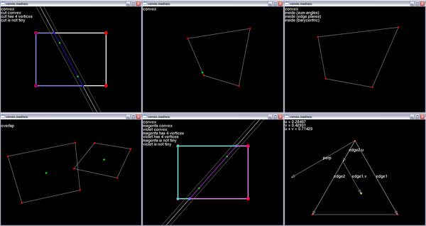
Convex madness demo 02 (with somewhat nicer split function and with overlap fixed)
prev: creating a simple polygon class / struct, displaying it with OpenGL next: simple 2D collision detection, space-game, arcade-game